Ceramic Valve Solutions for Flue Gas Desulfurization
KOWOV ceramic valves are designed for demanding FGD conditions involving abrasive slurry, corrosive chlorides, erosion, corrosion and crystallization
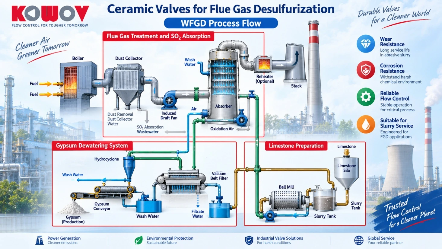
Flue gas desulphurization (FGD) systems are widely used in power plants and other industrial facilities to remove sulfur dioxide (SO₂) from flue gas
In wet FGD processes, limestone or lime reacts with sulfur dioxide inside the absorber. The process produces gypsum slurry and other solid-containing liquids that must be reliably transported, isolated and controlled
The combination of abrasive solid particles, chloride-containing process water, corrosive chemicals, scaling and crystallization places demanding requirements on valves used throughout the FGD process
KOWOV ceramic valves are designed for these severe operating conditions, providing reliable shut-off and flow control while reducing valve replacement and maintenance requirements
Target Industries
- Power Plants
- Steel Plants
- Mining & Mineral Processing
- Chemical Plants
- Municipal Solid Waste Incineration
- Cement Plants
Ceramic valves can be installed at critical slurry feed, circulation, isolation and control points throughout the FGD process
Typical Ceramic Valve Installation Points
- Limestone slurry tank outlet
- Limestone slurry feed line
- Absorber slurry inlet
- Gypsum slurry recirculation line
- Hydrocyclone inlet and outlet
- Belt filter feed line
- Filtrate water line
- Process water recirculation line
- FGD wastewater line
Typical Operating Conditions
Operating Conditions
FGD valves operate in solid-liquid two-phase media containing abrasive particles and corrosive ions. The operating conditions vary according to the plant, process design and valve installation point
Typical Reference Conditions
| Item | Typical Description | Characteristics |
|---|---|---|
| Process Media | Limestone slurry, lime slurry and gypsum slurry | Abrasive and corrosive |
| Fluid Type | Solid-liquid two-phase flow | Contains suspended solids |
| Working Pressure | Typically 6-16 bar | PN16/Class 150 commonly used |
| Differential Pressure | Typically ≤6 bar | Depends on valve location |
| Temperature | Typically below 100°C | No severe thermal shock |
| Solids Content | Approximately 20-25% in typical applications | High solids concentration |
| Particle Size | Approximately 10-100 μm in reference applications | Fine particles cause erosion |
| Chloride Content | Up to approximately 600 ppm in reference applications | Risk of chloride corrosion |
| Valve Size | Typically DN25-DN200 | Other sizes available on request |
Typical Process Media
Limestone Slurry, Hydrated Lime Slurry, Lime Slurry, Milk of Lime, Gypsum Slurry, Fly Ash Slurry, High-Chloride Process Water, FGD Wastewater, HCl Scrubber Water, Wash Water and Solids-Containing Filtrate
Characteristics of FGD Operating Conditions
Combined Erosion and Corrosion
High-velocity slurry and suspended solid particles continuously impact the valve flow passage and sealing surfaces. At the same time, corrosive ions attack exposed metallic components
The combined action of mechanical erosion and chemical corrosion results in rapid material loss and premature valve failure
Scaling, Crystallization and Wet-Dry Cycling
Sulfates, sulfites and other dissolved salts may penetrate surface linings and deposits. During shutdown or drying, these salts can crystallize and expand
Repeated wet-dry cycles may cause deposits, valve jamming, cracking, blistering or separation of conventional lining materials
Deterioration of Non-Metallic Linings
FGD slurry and corrosive process water may affect rubber and resin linings through swelling, softening, permeation and chemical degradation
Typical failures include
- Swelling
- Delamination
- Blistering
- Cracking
- Lining detachment
- Loss of substrate protection
Acidic Condensate and Low-Temperature Corrosion
Acidic components in flue gas and condensate, including HCl, HF and sulfur-containing compounds, may cause severe corrosion when the temperature falls below the acid dew point
This is especially important at positions exposed to corrosive gas, condensate or wash water
Process Pain Points
Conventional Valve Materials and Designs
Common valve types used in FGD systems include:
- Globe valves
- Eccentric butterfly valves
- Plug valves
- Metal ball valves
- Rubber-lined valves
- Resin-lined valves
Typical metallic materials include 316L stainless steel and, for more corrosive applications, Hastelloy C-276
However, material selection alone does not fully solve the combined problems of abrasion, erosion, corrosion, scaling and crystallization
Typical Valve Failures
Conventional valves may experience
- Rapid wear of the valve ball, disc and seats
- Corrosion and pitting of metallic wetted parts
- Damage to sealing surfaces
- Leakage after repeated cycling
- Scaling and material accumulation
- Increased operating torque
- Valve jamming
- Lining swelling or delamination
- Frequent maintenance and replacement
Short Replacement Cycles
In some severe FGD applications documented by KOWOV, conventional valves required replacement after only several months of operation
Typical historical replacement intervals included:
- Control valves: approximately 6-10 months
- On-off valves: approximately 12-30 months
Actual service life varies according to the medium, flow velocity, pressure drop, solids content, valve design and operating frequency
Maintenance and Shutdown Losses
Frequent valve failure may result in
- Reduced absorber capacity
- Environmental compliance risks
- Increased maintenance and cleaning costs
- Temporary piping and repair work
- Higher consumption of water, electricity and chemicals
- Frequent system flushing
- Shortened equipment service life
- Unplanned shutdowns and production losses
Improvement Opportunity
FGD service places much higher demands on valve wear and corrosion resistance than ordinary water or utility service
Frequent failure of conventional valves can become a major restriction on the continuous and stable operation of an FGD system. This creates a strong demand for improved valve materials, structures and application-specific solutions
Why Choose Ceramic Valves?
Superior Abrasion & Erosion Resistance
Composition of Limestone Slurry and Gypsum Slurry
The solid components include CaSO₄·2H₂O, CaCO₃, MgCO₃, inert substances, and sand/silt. The hardness of these solid particles can reach up to HRC 72
Given the installation locations and critical functions of slurry control valves, proper valve selection is extremely important for reliable on-site operation
Superior Corrosion Resistance
The corrosive ions present include SO₄²⁻ and Cl⁻
Characteristics of Desulphurization Media in Power Plants
As indicated by the composition of desulphurization slurry, the media in power plant FGD systems contain both hard solid particles and highly corrosive chloride ions (Cl⁻), making this one of the most demanding service conditions
The hardness of these solid particles can reach HRC 72, which is comparable to that of hard alloys
All-Ceramic Trim Structure
The smooth, dead-zone-free flow path provides equal-percentage or quick-opening flow characteristics
The abrasion-resistant ceramic components retain their shape during long-term operation, helping the valves keep a tight seal; tested in accordance with GB/T 26480, they show no visible leakage
A specially designed ceramic ball trim is used to meet slurry atomization requirements, delivering superior cost reduction and improved operating efficiency
Quality Promise
Minimum service life
- Control valves: more than 3 years
- On-off valves: more than 7 years
The lower replacement frequency reduces downtime and associated losses, cuts operating costs, and improves plant safety
Conclusion
Ceramic slurry valves solve problems caused by corrosion, abrasion, erosion, and scouring. Successfully applied in flue gas desulphurization systems, they are the optimal choice for demanding FGD applications
Application References
Proven Performance in Power Plant FGD Systems
KOWOV ceramic valves have been used in power plant FGD systems for more than two decades
Selected References
- Huaneng Luohuang Power Plant, supplied since 2003
- Datong No. 2 Power Plant, supplied since 2003
- Junliangcheng Power Plant, Tianjin, supplied since 2004
- Guohua Ninghai Power Plant, supplied since 2006
Documented Service Life in Selected Applications
- On-off valves: up to 8 years
- Control valves: up to 5 years
In selected FGD projects, KOWOV ceramic valves have been used to replace imported ceramic valves and conventional metal control valves, helping customers reduce maintenance frequency and extend valve service life
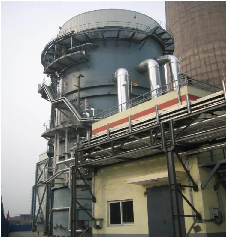
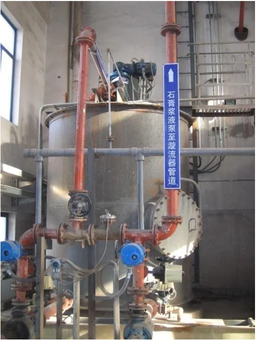
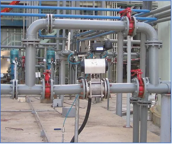
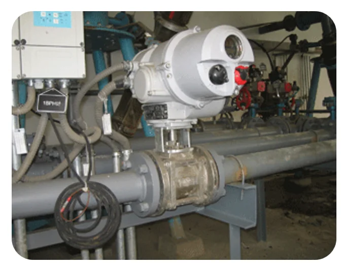
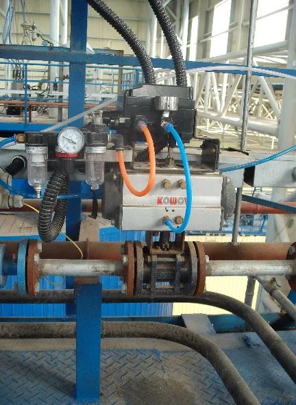
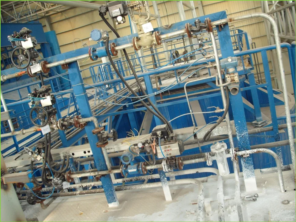
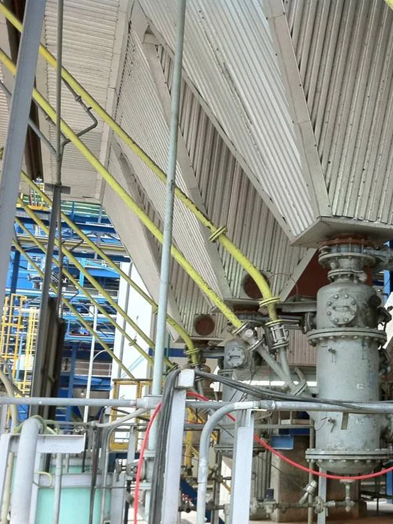
Flue Gas Desulfurization: site photographs
Commonly Used Products
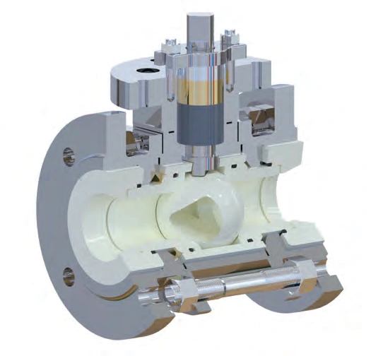
FCCV1
Ceramic Ball Valve
A bidirectional ceramic ball-valve architecture for on-off duties where abrasion, corrosion or deposits affect the sealing path
View FCCV1
ELCV
Economical Ceramic Ball Valve
A compact ceramic ball-valve option for duties that need ceramic sealing surfaces without the architecture of the higher-severity FCCV families
View ELCV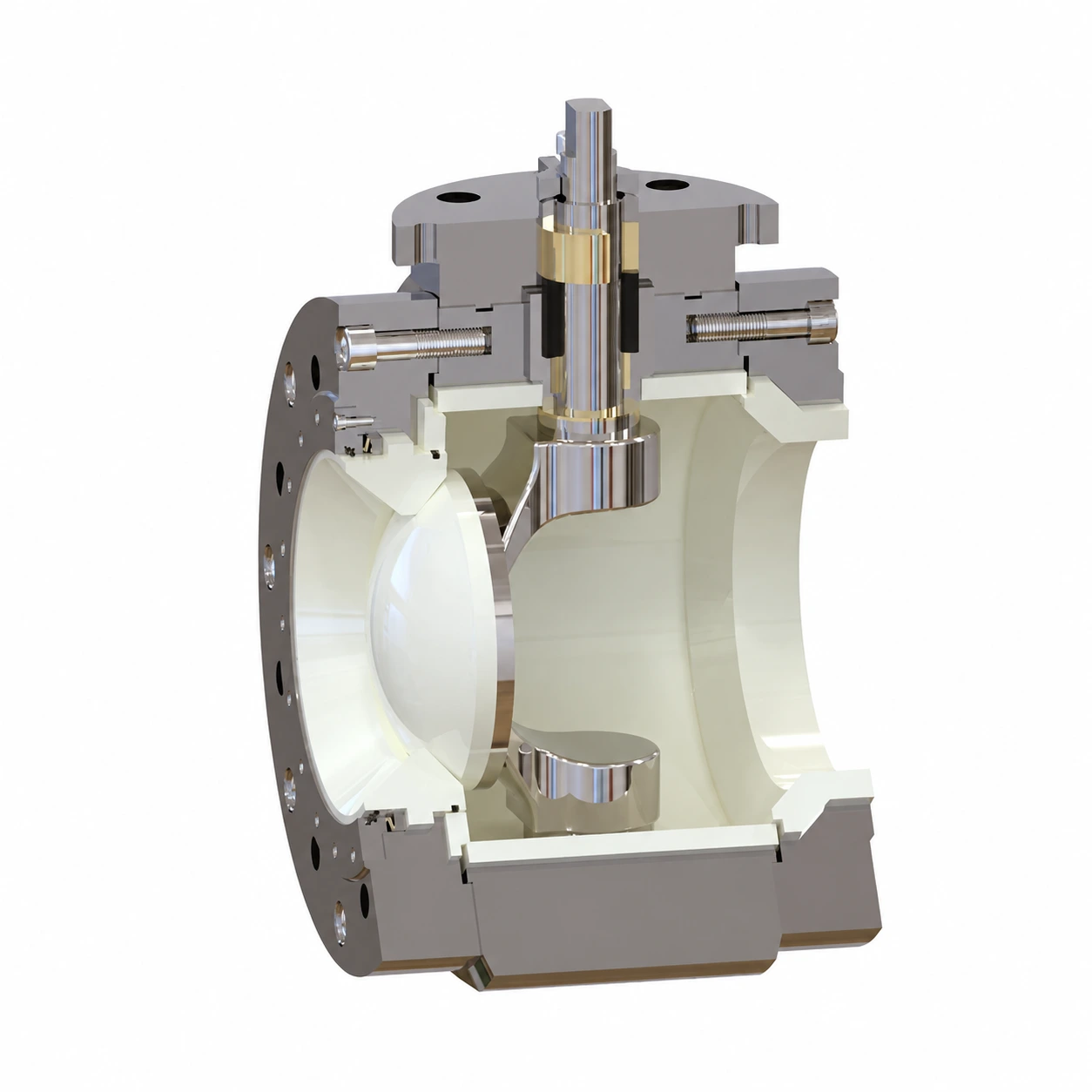
FCRV
Ceramic C-Type Rotary Valve
A rotary C-segment flow path for regulation, shearing deposits and handling viscous or particle-bearing media
View FCRVContact Us
Talk to our team about your flue gas desulfurization application
Discuss your application